UK GPI Supplier
Great Plains Industries
Great Plains Industries are one of the leading manufacturers of fluid flow meters, flow sensors, flow monitors and flow control equipment. GPI have become the first choice supplier for fuel meters, water meters, chemical meters and general purpose flow measurement.
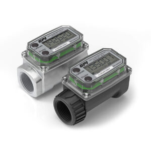
As a UK GPI supplier we have an extensive range of digital turbine flow meters, suitable for low to medium viscosity fluids. These come with a choice of construction materials and end fittings. Most GPI digital turbine meters are ATEX certified for hazardous areas and are available in a range of materials including: Aluminium, Stainless Steel, Brass, Nylon, PVC and PVDF.
Choosing the right Flow Meter
When considering the use of a flow meter within an application system, it will count the amount of fluid in that cycle as it is being dispensed or moved. When the cycle has finished it will show the total of the fluid that has just been transferred, this is called a batch total and is usually resettable before another cycle (mainly used for fuel dispensing). This means there are two totals on most flow meters. One being the batch total and the other being the cumulative total which is the amount of fluid transferred over the whole lifetime of the flow meter. This is usually non-resettable.
Most flow meters will either be digital or mechanical. A battery powered flow meter usually has a digital display. A mechanical flow meter will have a tick over digit display. A factor to consider when when selecting a flow meter is accuracy. The accuracy rating for a flow meter will depend on the flow range of the meter. For example, the fluids flow rate will need to meet the minimum flow to maintain accuracy.
Flow rate is another consideration when choosing a flow meter. The most common flow rate when it comes to flow meter is litres per minute (lpm). It is important to choose a flow meter that can cope with the flow rate of the application. For example, refuelling a larger vehicle would require a high flow rate than a smaller one like a car or motorcycle.
What is a Flow Meter?
A flow meters use is to check the quantity or fluid that is being moved from one place to another. This can often be from a tank to a vehicle. Flow meters usually display a numerical figure in a chosen measurement, this can be gallons, litres, or cubic feet and for some flow meters more options are available. The numerical figure can have either digital or mechanical faces and in some cases they may not have a local display. In this situation they work by sending out and electrical pulse to a remote display located elsewhere. There are a few different types of flow meters as the vast amount of different fluids and transfer applications that use them. There are 3 main types: Turbine, Oval Gear or Nuntating Disk style meters. Even though they all work differently they all do the same job.
Turbine Flow Meters

A turbine flow meters main feature is a rotating turbine. The flow rate is recorded as the turbine rotates and the fluid passes over it. As the fluid rotates the blades it starts the rotor in motion. When the fluid is flowing steadily and a consistent speed is reached it is proportional to the fluids velocity. If a turbine flow meter is digital a blade on the turbine would have a sensor or magnet on it. This would send a pulse to the computer on each rotation. An example of a good digital turbine meters is the GPI G2 Industrial Grade range.
Oval Gear Meters

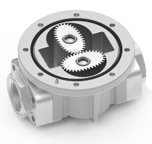
Oval gear flow meters use at least two gears which rotate at right angles to each other, this creates a T-Shape. In the centre of the flow meter the teeth of the two gears always mesh, this means that no fluid can pass through this point. The gears rotate when the fluid pushes against them, as this happens it moves the fluid in the measuring chamber into the meter's outlet. At the same time, the fluid that is entering the inlet will be passed into the other measurement chamber as the other one close. This process continues to alternate as the gears rotate and the fluid flows through the alternating chambers. The flow is measured by magnets in the rotating gears which then transmit a signal to an electric reed switch, based on the speed of rotation.
Nutating Disk Flow Meters

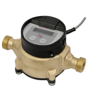
A nutating disk flow meter consists of only one essential moving part which is accurate and fairly inexpensive. The operating cycle is simple but can be difficult to understand its operation without seeing the device in person. The meter consists of a metering chamber with conical top and bottom and spherical sides. A disk passes into a central sphere which divides the chamber into two portions. The disk is confined to be at an angle not normal to the axis of symmetry of the chamber.
A radial plate (diaphragm) separates the chamber so that the fluid entering causes the disk to wobble (nutate), with fluid flowing above and below the disk. When the disk has completed one wobble the fluid exits the chamber. The wobble represents a specific volume of fluid passing through the chamber. During each wobble of the disk, the pin attached to the top of the center sphere, the normal disk completes one circle. Counting the number of revolutions completed determines the volume of fluid that has passed through the meter.
Contact Us
This is an information and enquiry site only. For more information please contact us or shop online at www.fueldump.co.uk
The Office
Atkinson Equipment Ltd
Moat Road, West Wilts Trading Estate
Westbury, Wiltshire
BA13 4JF
Phone: 01373 822220
Email: sales@fueldump.co.uk
Business Hours
Monday - Friday 8:30am to 5:30pm
Saturday - Closed
Sunday - Closed